A Fresh Set of Eyes
Introduction
Embarking on a task that intertwined my experience and knowledge of amateur radio, environmental sciences, and satellite communication, December of 2021 marked a breakthrough in my attempts to receive and decode an image captured by a satellite soaring high above in orbit. Guided by my long-standing desire to see earth from space, I constructed a ground station made up of antennas, receivers, and a rat’s nest of wires, tuned specifically to hone in on the faint signals emitted by the satellites NOAA-15, NOAA-18, and NOAA-19. Over the following months, I successfully captured and decoded five images from low earth orbit.
The three satellites, NOAA-15, 18, and 19, are incredible marvels of engineering. The images these satellites capture are extremely valuable to scientists and researchers. They offer insights into weather patterns, CO2 emissions, and oceanic currents and conditions at a scale and quality never before seen.
In this blog post, I will share the fundamental concepts explored, the raw data I captured, the images I processed, and the setup I used, and I will explain the decision making process behind my steps.
Selecting a Satellite
Satellites, being in a stable orbit around a central body, follow predictable paths which can be defined by equations and computed using software. Their orbital parameters, which define their motion, are published at launch and are constantly updated by ground stations operated by the institutions that launch them. There are plenty of online databases which host the orbital parameters, frequencies, and operational statuses of thousands of satellites, such as N2YO, Heavens-Above and OSCAR.
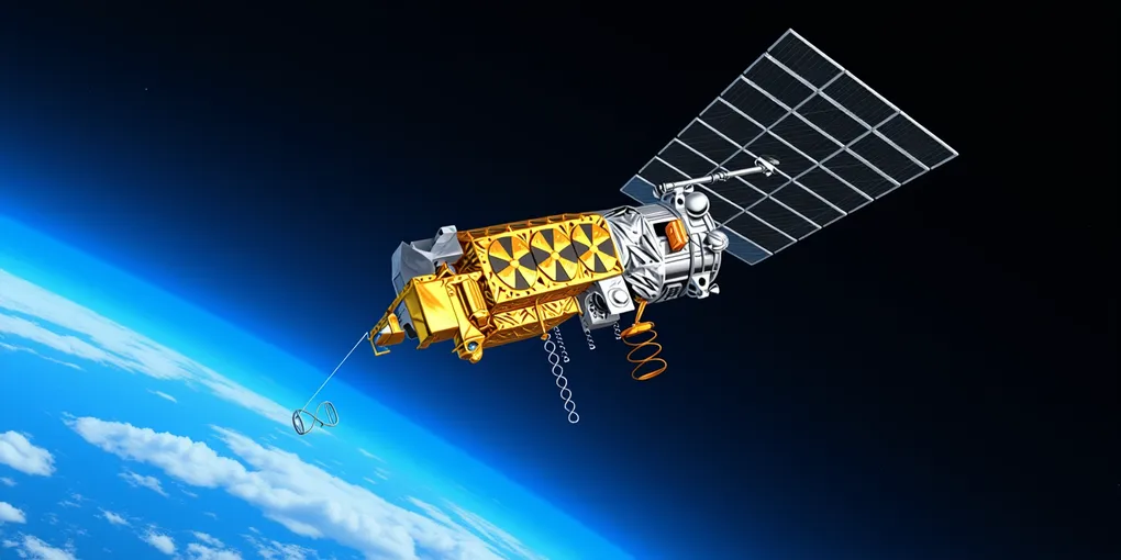
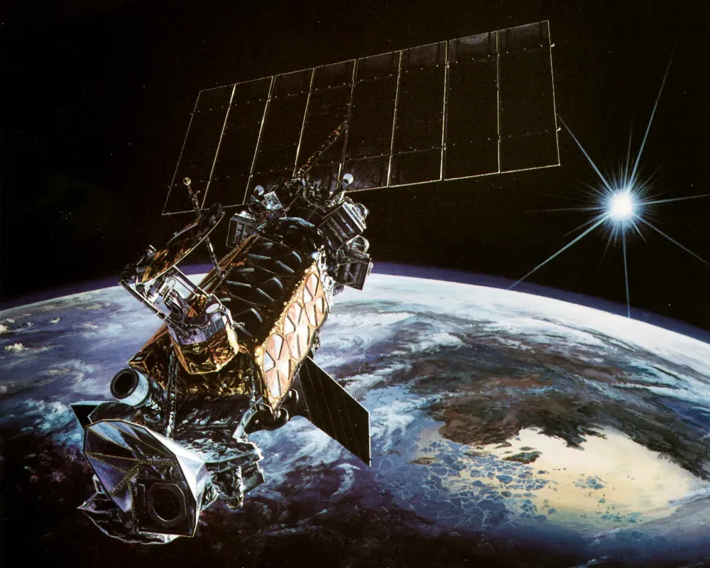
The satellites NOAA-15, NOAA-18 and NOAA-19 stuck out as great candidates for many reasons. They are based on the Advanced TIROS-N satellite bus and carry a wide array of instruments. Different data types are transmitted on different frequencies which are listed on the above sources. These satellites transmit reduced resolution images at 137.62 MHz, 137.9125 MHz and 137.10 MHz respectively in an analog image format called Automatic Picture Transmission (APT).
The image signals produced by the three satellites can be received using cheap, DIY hardware. They are low frequency and horizontally polarized, meaning they can be picked up by a simple dipole antenna.
The Ground Station
After selecting the best satellites, it was time to build a ground station. My goal was to build the ground station as quickly and cheaply as possible while still using reliable components. Having purchased software defined radio (SDR) equipment before, I knew the perfect places to look.
Required Hardware
Tuner Dongle
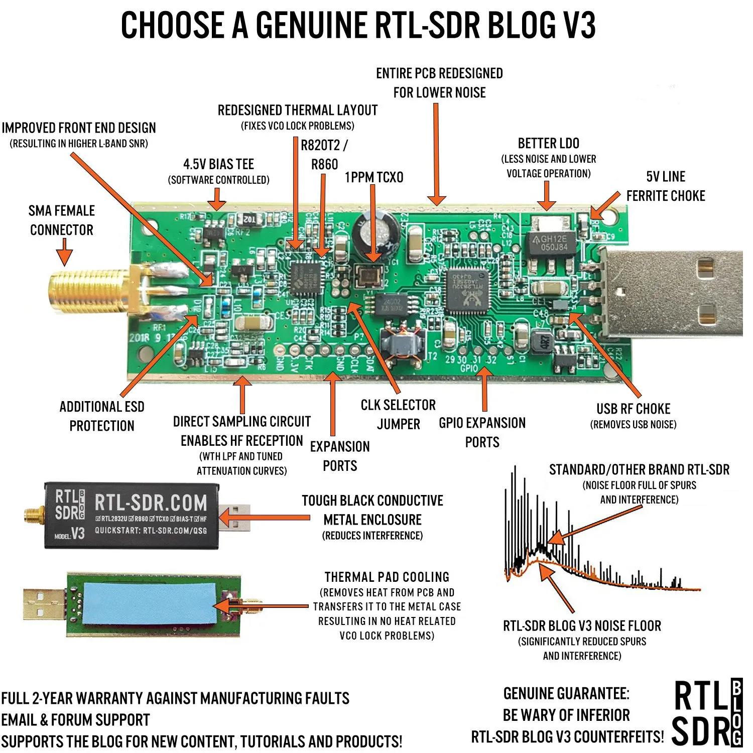
To pick up and record any signals at all, I needed an SDR tuner dongle. This piece of hardware connects to an antenna on one end and a computer on the other, and allows the computer to control its internal radio. It also converts the received signals from the antenna into a digital signal which can be understood by the computer. This is necessary for precisely honing in on satellite signals as well as capturing them digitally for processing, so without it, the project would go nowhere. Due to its low price point and high quality components, I chose the RTL-SDR Blog V3 R860 (R820T2) RTL2832U 1PPM TCXO SMA Software Defined Radio.
Low Noise Amplifier
Another important piece of hardware is an amplifier (amp). The amp is connected between the tuner dongle and the antenna, and is powered by bias tee power from the tuner dongle. It boosts the received signals without adding noise, which makes signals and the images extracted from them much clearer. Because of its simple connectivity with the chosen tuner dongle, I chose the RTL-SDR Blog Wideband LNA.
Dipole Antenna
After selecting the tuner dongle and the amp, I needed an antenna to receive the signals. Given the horizontal polarization of the signals emitted by the satellites, a dipole is the ideal antenna construction for receiving them. RTL-SDR has an excellent dipole antenna kit, featuring extendable antenna which can be extended or retracted for the best reception with any given frequency. Staying consistent with the rest of the equipment so far, I chose the RTL-SDR Blog Multipurpose Dipole Antenna Kit.
Tripod
Next, I needed a structure to support my antenna and hold it in the proper orientation. The RTL-SDR Blog dipole kit is designed to mount to a tripod, so I went hunting for the cheapest tripod I could find given that the antenna weighs much less than a camera. I found that Target has a decent selection of tripods for dirt cheap, so I went to the store to search for the perfect one. The tripod I purchased is the Sunpak TravelMate 50/B 50” Tripod. Despite its cheap construction and poor material quality, it works great for this lightweight antenna.
Handheld Radio
In order to monitor multiple frequencies at once and confirm acquisition of signal, I decided it would be useful to have an amateur ham radio on hand. I didn’t need an expensive radio, just a simple handheld contained in one unit. For this task, I chose the reliable Baofeng UV-5R. It’s a controversial radio for many reasons including its scarily high transmission power and low quality electronics, but it works great to confirm acquisition of signal.
Additional
Additional pieces of equipment I purchased to set up the ground station correctly include a tape measure to set the dipole antenna length, a protractor to set the dipole antenna angle, a bubble level, a notebook for field notes, a compass, and a Casio fx-991CW calculator for some math help.
Assembly
Assembling the ground station takes about six minutes. It’s simple process, so the ground station can be transported disassembled and then assembled on site. Here is the assembly process, taken from my field notes:
- Remove tripod from bag and deploy. Remove the camera mount.
- Attach dipole base by screwing it onto the camera mount.
- Use the tape measure to precisely extend each of the two antennas to 1/4 of the wavelength of the chosen frequency.
- Attach antennas by screwing them into the dipole base.
- Attach camera mount, dipole base and antennas to the deployed tripod.
- Use protractor to angle the dipole antennas 120º apart.
- Align dipole assembly horizontally to the ground.
- Use a compass to point the center of the dipole exactly north.
- Tilt dipole to align with satellite elevation.
- Connect one end of coaxial extension cable to dipole base and other to amplifier input.
- Connect amplifier output to tuner dongle.
- Connect tuner dongle to laptop and begin software initialization.
- Do not forget to enable bias tee power to supply amplifier with power.
After following these steps, the hardware setup is complete, and the remaining work has to do with software.
Software
While hardware is important for receiving satellite images, it is only one half of the equation. Software is required to compute satellite passes, locate signals, store recorded data to the computer, process it, and export the final images. For this project, I used a wide range of different softwares for individual tasks.
Satellite Tracking/Pass Predictions
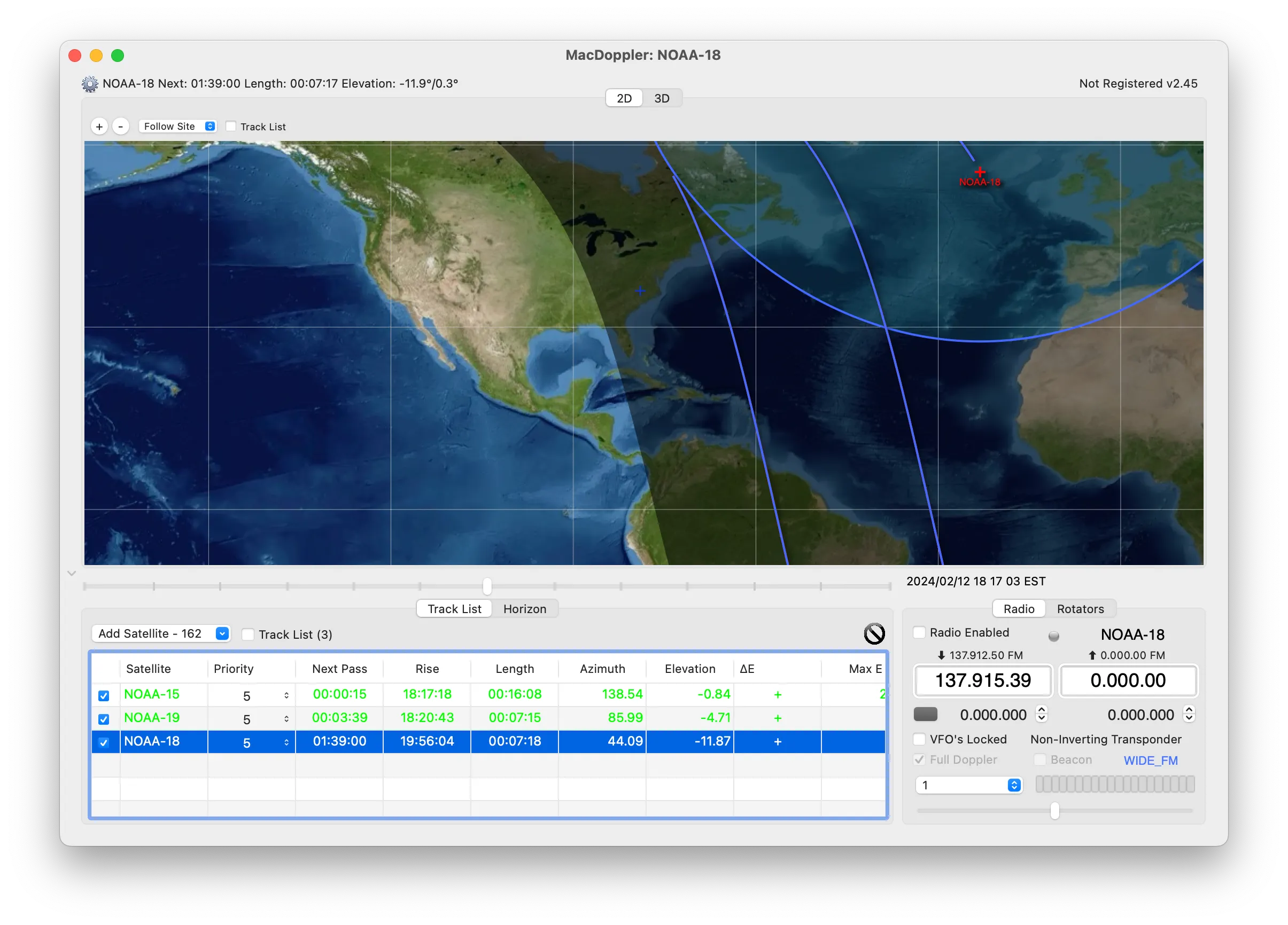
A key step of receiving images from satellites is figuring out the times when the receiver will have a line of sight view of the satellite. To do this, I needed to use a software which would allow me to accurately predict when the satellite would be overhead. A satellite tracker software gives you the ability to view the locations of satellites of interest, predict their motion relative to your location, and compute important details like elevation, azimuth and acquisition of signal times. For this task, I used MacDoppler. I chose it because MacDoppler has built it functions to download satellite telemetry data (Keplerian Elements) from multiple sources and make predictions based off of that data. It also has excellent ground track visualization.
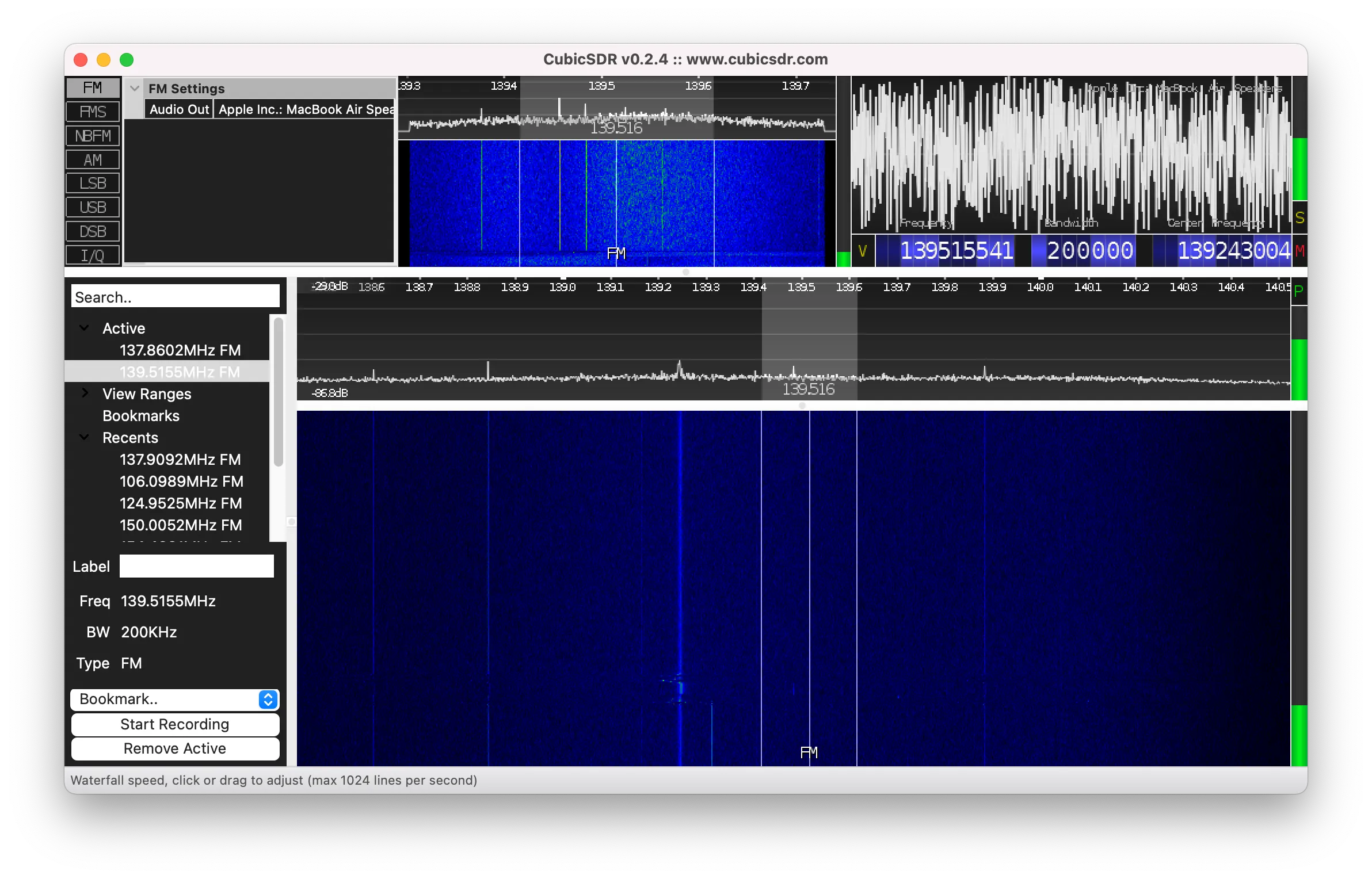
Software Defined Radio
The RTL-SDR Blog V3 tuner dongle I chose is compatible with a wide range of software suites. While searching for the perfect program, I was specifically keeping my eye out for open source software compatible with macOS. The best macOS app I found is CubicSDR. It’s reliable, can be built on your own machine, and provides a wide range of controls for the tuner dongle. It’s important to note that it no longer seems to function on macOS versions 14.0 and above. This issue can be resolved by dual booting macOS Big Sur along side the main operating system and running CubicSDR inside Big Sur.
Something that I found out the hard way is that the RTL-SDR Blog V3 tuner dongle does not have bias tee power enabled by default. This means that without intentionally enabling it, the amplifier will not function. To get bias tee power working, I downloaded the rtl-sdr-blog repo from Github and built it using make. From there, I used the rtl_biast binary to enable bias tee power. A tutorial can be found in the RTL-SDR Blog V3 Dongles User Guide.
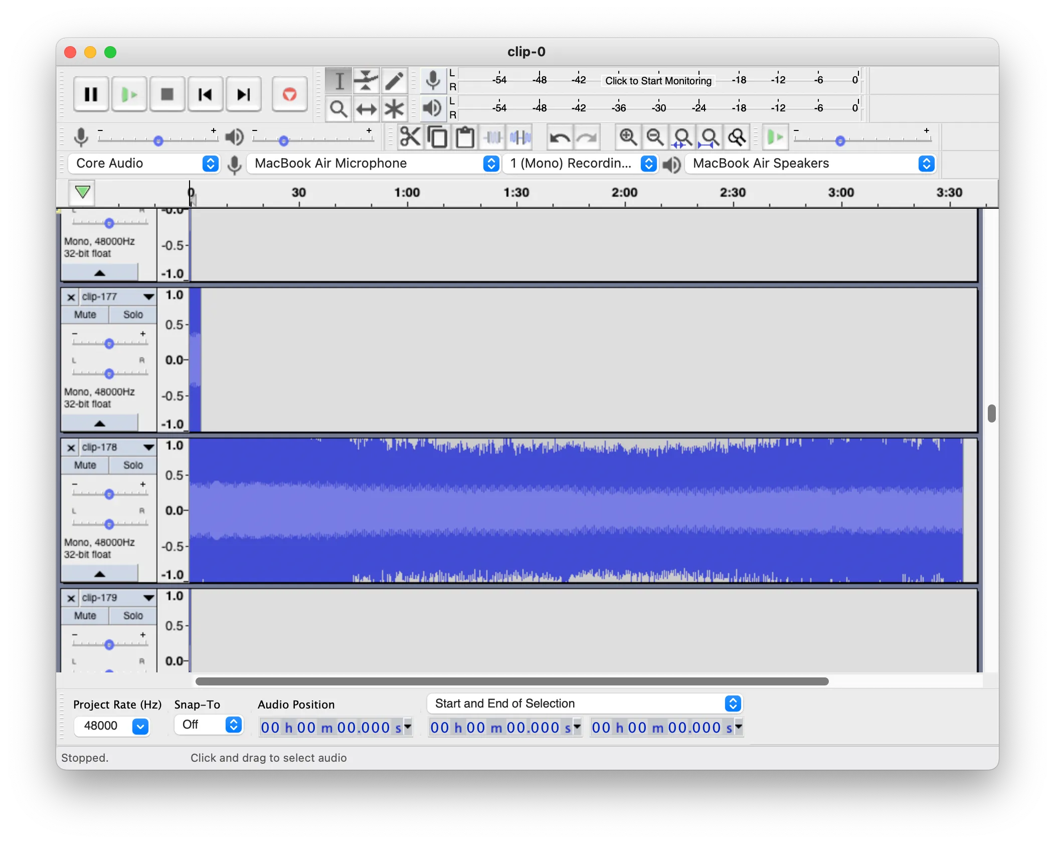
Audio File Processing
After recording signals using CubicSDR, the specified recording directory gets filled with short audio files. Before attempting to decode the received data, they need to be stitched back together into one file. To create one file, I used Audacity. Audacity offers a plethora of tools for manipulating, combining, and exporting audio files. After opening Audacity, I dragged the directory of audio files into the timeline and used the align tool to align them end to end. Then, I used the mix and render tool to stitch them together. After that, I exported them as a .wav file.
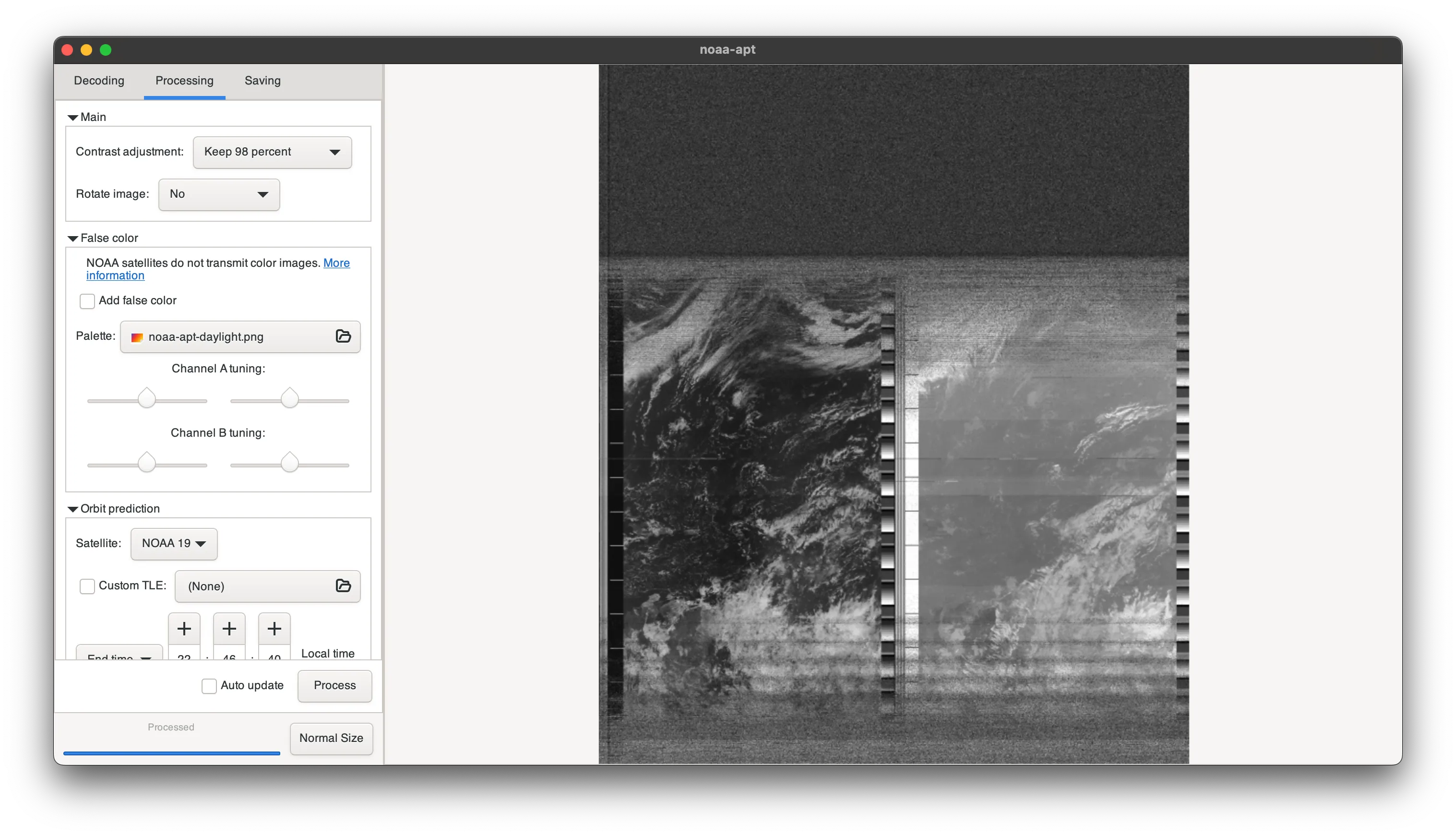
Decoding
With a single audio file ready, I needed a method to decode it to an image. The data transmitted by NOAA-15, NOAA-18 and NOAA-19 is encoded in the APT (Automatic Picture Transmission) format. Searching online for a software to decode it, I found a Github repository called NOAA-APT. NOAA-APT has a graphical interface and is almost entirely written in Rust, which is a high performance, ahead-of-time compiled language. It can be compiled using the Rust toolchain and the build process can be found here. After running the binary, the audio file can be imported and decoded into an image.
The Software Workflow
All of the mentioned softwares can be combined into a single workflow, which allowed me to quickly convert my recordings from raw data to final images. Here is the process I followed, according to my field notes:
- Open MacDoppler and add NOAA-15, NOAA-18, and NOAA-19 into the list of tracked satellites.
- Use the predict function under the options menu to make a set of pass predictions for each satellite.
- Choose ideal satellite pass based on schedule and write downlink frequency, elevation, azimuth, and acquisition of signal (AoS) times of selected satellite into notebook.
- Travel to open space free of radio interference and nearby structures and arrive 30 minutes ahead of AoS time.
- Follow ground station setup guide and enable bias tee power using rtl_biast after connecting tuner dongle to laptop.
- Launch CubicSDR and select “Generic RTL2832U OEM” from the list of devices.
- Enter satellite frequency into the frequency box below the waveform and check for interference.
- Specify the recording directory before AoS.
- Wait until AoS and begin recording when signal appears on waterfall view.
- Teardown ground station after loss of signal.
- Drag recording directory into Audacity and align clips end to end, then mix and render to a single track.
- Export combined clips to .wav format.
- Launch NOAA-APT and import .wav file.
- Select decode, and then select process. Ensure parameters are set for the correct orientation of the image.
- Export to .png and store all used data to the archives.
After following all of these steps, I had my first ever satellite image.
Gallery
January 30, 2022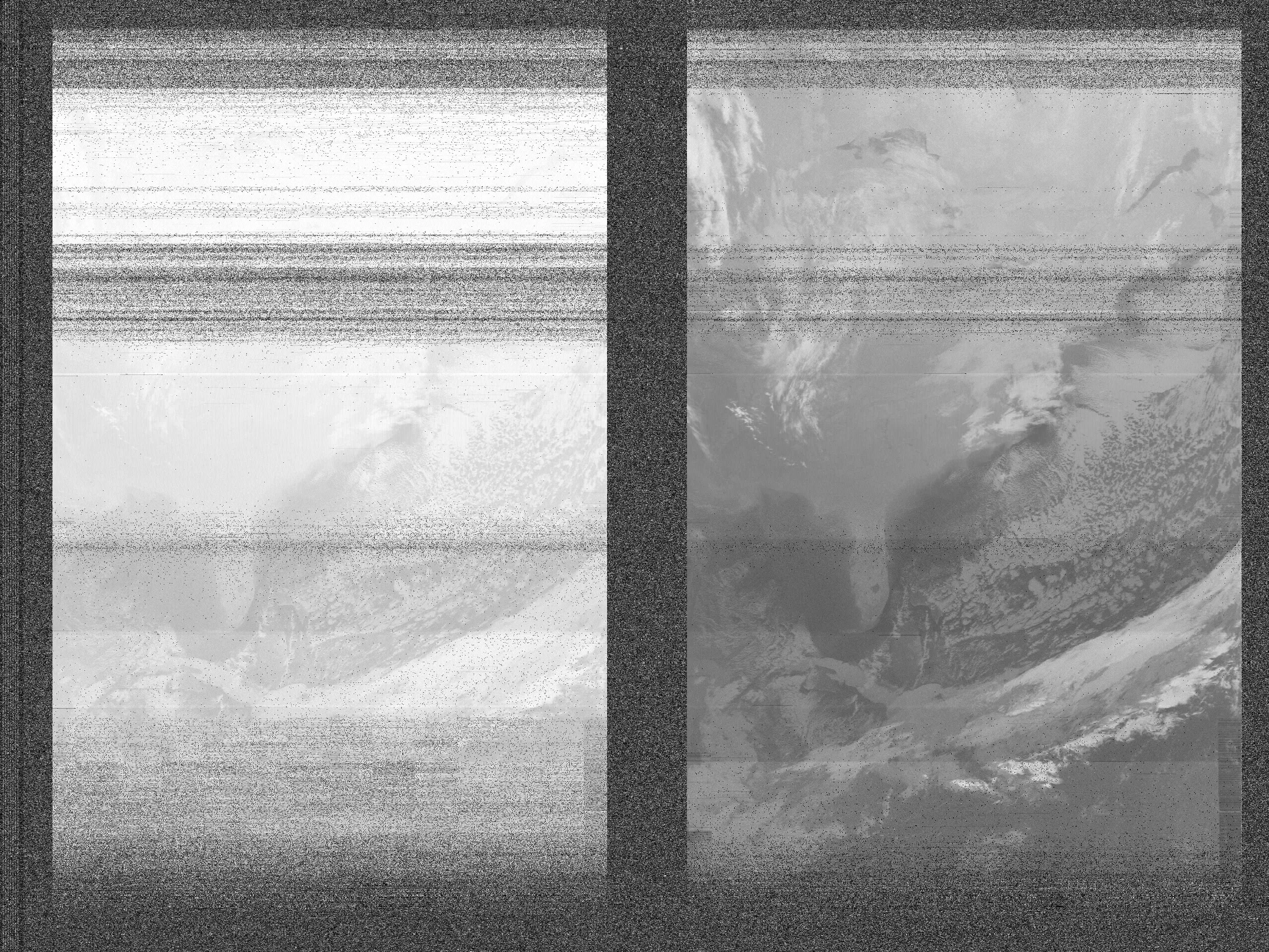
February 13, 2022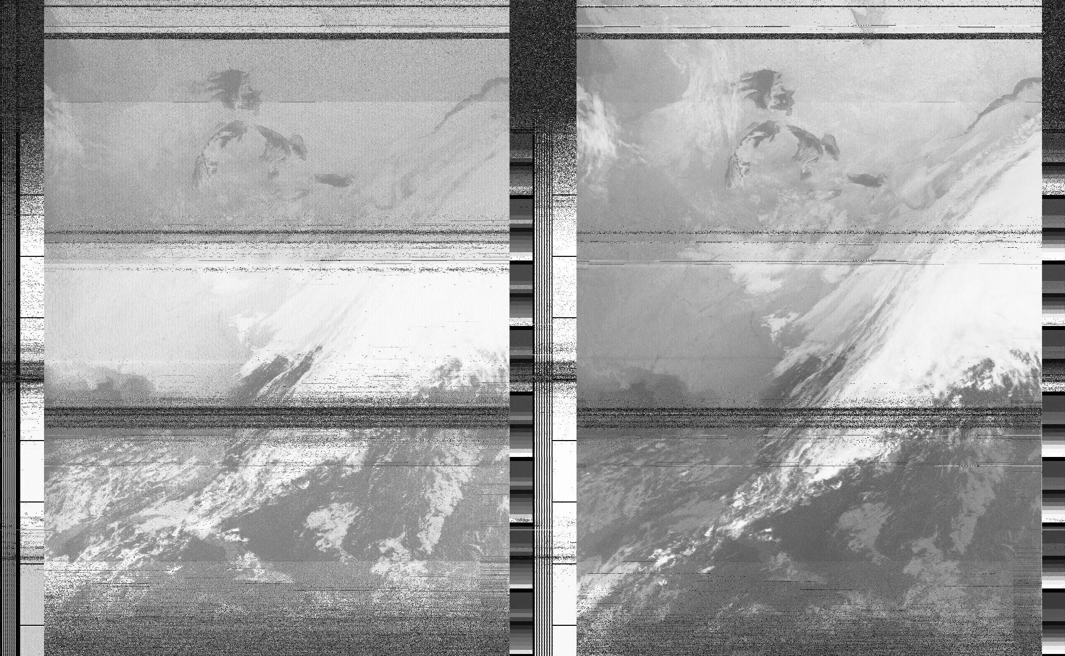
February 19, 2022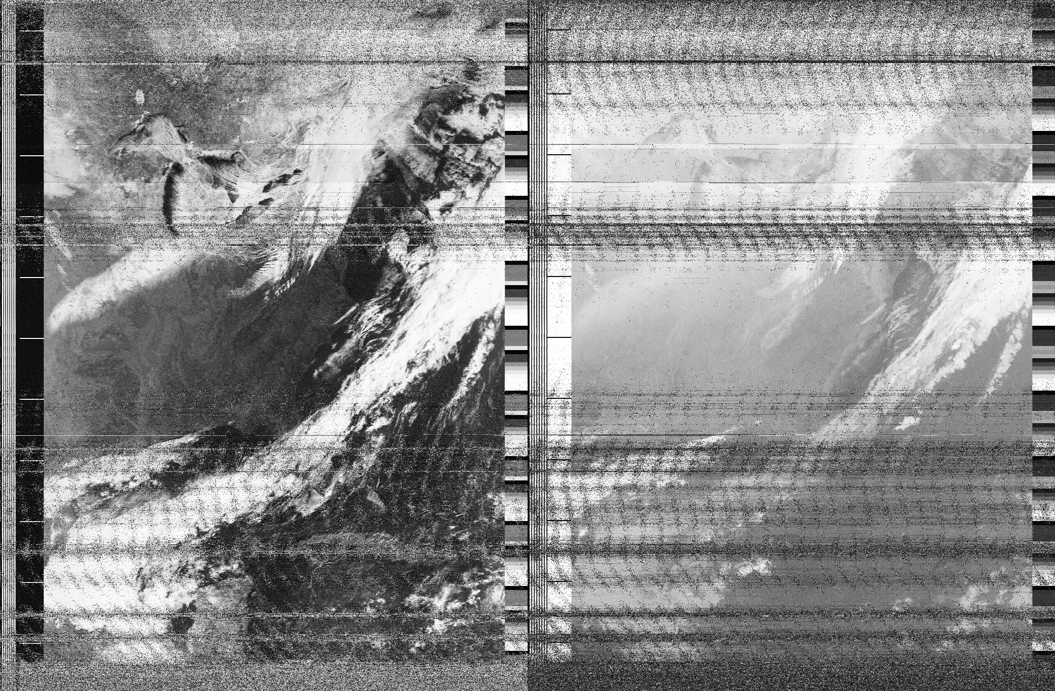
March 8, 2022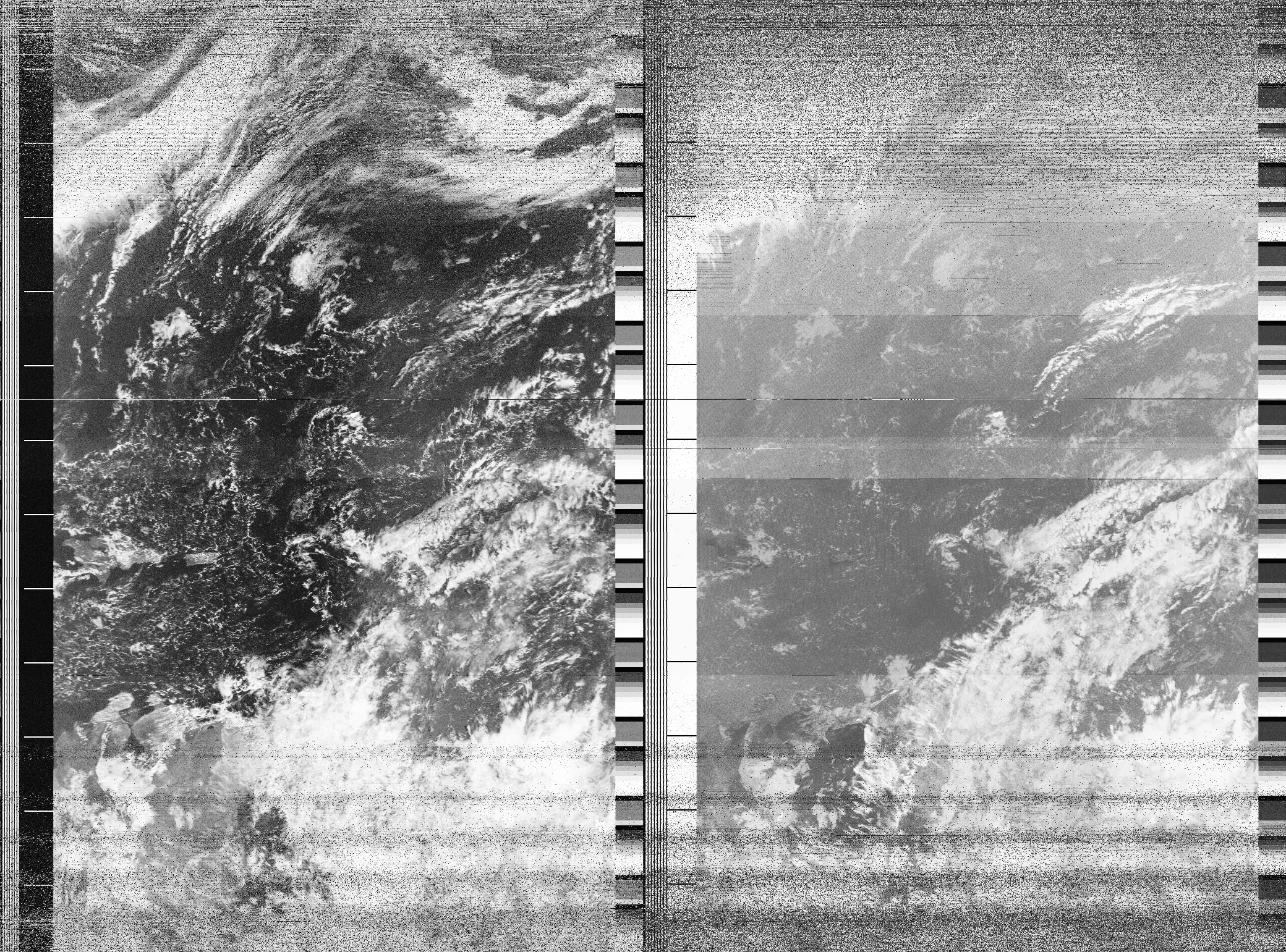
February 17, 2023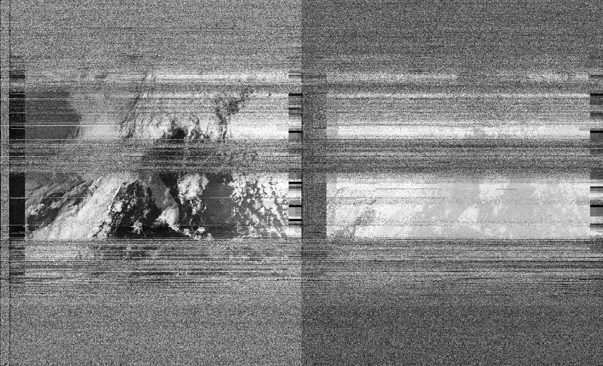
Conclusion
Thank you for taking the time to read to this point. This project has been the most enjoyable thing I have ever worked on. I want this blog article to act as encouragement for everyone reading to never lose their curiosity, and to continue to search for answers. Nothing is out of reach until you’ve attempted it, and without trying, success can never be known. Science is for everyone.